|
This site is sponsored by Corporate Systems & Solutions and Real World Software Architecture. |
How does the architect get their architecture propagated throughout analysis, design, and the construction phase? I have only found one way to successfully do this. It is what I refer to as Restrictive Development.
Restrictive Development pulls the architectural pain points out to an abstraction layer through the use of architectural project level patterns. The patterns are cataloged, described, and examples are documented. The phases that begin after the architecture begins use the patterns as a guide for what is allowed to be implemented along with an architecture synthesis that provides the implementation of all the patterns.
Keep in mind these are architectural level patterns, not design level patterns. The design phase will be guided by these patterns and may end up with it's own catalog of design level patterns. If design finds a need to extend, alter, or add to the patterns in the architectural level patterns, they must be approved of first and then architecture is updated to reflect the additions, changes, or extensions. Also keep in mind the changes or additions must be architecturally significant to be added to the these patterns. Several patterns may exist at a design level that are module or component level in scope. Constant feedback is expected during all phases. Change is bound to happen throughout the iterations of module and component design and development, so your process must allow for it.
Most places I have been that do an architecture, do not have a propagation technique that allows for the architecture to guide the other phases of the project including analysis, design, and construction. This has caused a lot of places to consider architecture a waste of time, so they stop doing it. Most of the time you will find the only view they implement that is architecturally significant is the deployment view, and this view is usually put together after the construction phase just so they know what ended up living where.
The patterns result from an architectural synthesis that is build using production level coding standards. The architectural synthesis comments are compiled into an MSDN formatted help file to provide further guidance. The code produced supplies an implemented example of the patterns cataloged as well as a starting point for most parts of the project's construction phase.
I usually find two types of pattern catalogs are needed to cover the pain points of the architecture. Communication Patterns and Code Implementation Patterns. I have provided a summary of each along with one example of how each is documented.
Because this example was taken from a real project and I cannot disclose actual code samples or any part of the real data used from that project, I have only included the steps taken for the the code implementation example. I have made note where code samples were and where screenshots were. I have also altered tables, diagrams, and code to be generic instead of using the actual names used during the project. The listed steps should give you a pretty good idea of the detail need to support the documentation of a pattern.
On my latest project we are using the GAT to distribute the core components and are enforcing the patterns by providing guidance through recipes and wizards. I know that DSLs may some day help in the same context, but they are a bit too far off in the future to bother with right now. More on the GAT HERE.
The communication patterns are intended to define how the client software will communicate with the web service. These patterns are specific to the goals of this application and are not intended to provide guidance outside of the context of this project.
As with most patterns these are intended to be used together. Below is a diagram that shows how our communication patterns are tied together.
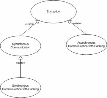
Figure 9: Communication Patterns
The encryption patterns cover both the client and server-side encryption. We use the WSE to provide encryption using X.509 certificates. We also used the WSE to enforce encryption policies. The policy put in place checks the messages going into the web service to ensure they were digitally signed and encrypted. It also checks the messages going into the client to ensure they have been encrypted. Our pattern of encryption ensures the encryption implementation takes place in the same way.
An example of the client encryption pattern is shown below in the sequence diagram.
Figure 10: Client Encryption Pattern
Using the ClientEncryption class found in the WinformsPOC namespace all the developer has to do is call the GetProxy() on the ClientEncryption class.
EXAMPLE:
ClientEncryption Crypt = new ClientEncryption();
GcWsPx = Crypt.GetProxy();
All the encryption logic is encapsulated in ClientEncryption class.
The code patterns are intended to guide developers through the process of adding functionality to the application. These patterns are feature based patterns and are to be considered in reference to the currently purposed architecture. If the architecture is changed, the implementation patterns may also need to be change.
Below is a diagram that shows all the different implementation patterns that will be covered. You will notice that they are not all interdependent. That is because they a feature centric. What this means is a new user interface feature may be implemented that may not effect any other layer of the application. The same is true of the database layer of the application. A new database object may be added the does not directly impact the user interface in any other layer.
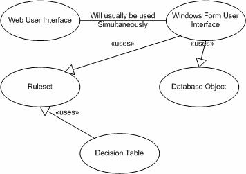
Figure 14: Code Implementation Patterns
The table below shows the code implementation patterns as they are related to the different layers of the application. The intention of the table is to show the layers the patterns apply too and the likelihood that code will need to be implemented at that layer. The layers that are considered included in the common pattern implementation of the pattern are shaded in that pattern’s column. This does not mean that the patterns can not be extended, but the reasons for an extension should be reviewed. Simplicity is the goal of using these patterns and any extensions to them may be introducing unnecessary complexity.
Code Implementation Patterns Table
Layer
Example found in current Application
Windows Form User Interface
Web User Interface
Ruleset
Decision Table
Database Object
Class Type
User Interface
Web Form
examplePage.aspx
M
R
U
U
U
Windows Form
example
R
M
U
U
U
Communication
Proxy
exampleProxy
R
V
U
U
U
Web Service
exampleWS
R
V
U
U
U
Business Layer Functionality Implementation
Business Functionality Classes
exampleBus
M
U
U
U
U
Rules Service Agent Classes
exampleServiceAgent
M
U
U
U
U
Application Object Implementation
Business Objects Definition Assembly
exampleData
M
V
U
U
U
Rule Objects Definition Assembly
exampleData
M
V
U
U
U
Data Access Layer
Data Access Classes
exampleData
M
V
U
U
R
Oracle Package
PKG_example
M
V
U
U
R
Oracle Tables
exampleTABLE
M
V
U
U
R
Rule Objects
Ruleset
exampleRS
M
V
R
R
U
Decision Table
exampleLookUp
M
V
M
R
U
Below are explanations of the codes used in the table.
· R – Code is required
· H – Highly likely that code will be required
· M – Code may be required in certain circumstances.
· U – Highly unlikely that code will be required
· V – Violation of the pattern and should not be implemented.
This pattern is the only pattern that is likely to cause the developer to have to implement code in each layer. This pattern should be propagated through the design phase and be the primary pattern used during development.
When functionality is added to the user interface that supports business logic from the user requirements, it will be very rare, if at all, for that user interface logic to only need code implemented at the user interface level. This will be especially true during initial development. Usually the functionality will be tied to rules or to data.
It is possible that the functionality uses preexisting rules, rules that can be implemented in user interface code, or that the new functionality uses preexisting data. In any of these cases only user interface code may have to be implemented.
The following example shows the recommended steps taken using this pattern. It includes a list of the steps taken and an overview of each. The example uses the addition of the user calculation functionality to the architectural synthesis.
STEP 1: Create Rule or Business Classes.
The intention of these classes is to house the data that will be used by the application to implement business objects and business rules.
***The code example would be shown here.***
STEP 2: Create Rules and any Decision Tables.
To create the rules and decision tables the developer uses the QuickRules.NET rules builder. Below are screenshots showing the user calculation rules project.
Note that this is also the step where Database objects would be built and DAL code would be implemented to handle the database communications. The user calculation did not require any database communication.
Screenshots of creating the rules and decision table would be included here.
STEP 3: Add Methods to the Proper Interface.
There are two primary interfaces used in the prototype, IRules and IExampleApp. They are used to define the functionality of the business objects and business rules.
The example functionality only used the Rules Engine so the functionality was added to the IRules interface.
Below are both of the interfaces, but the only IRules interface has code for the user calculation functionality, which is the last method in the interface.
***The code example would be shown here.***
STEP 4: Implement the Methods
The next step is to implement the method’s functionality. There are two possible places to implement the methods. FinancialBus, which implements IGuidelineCalc, is for the implementing business functionality. ServiceAgent, which implements IRules, is for implementing rules functionality. The user calculation’s implementation of GetSCUserData is shown below.
***The code example would be shown here.***
STEP 5: Implement the Web Methods.
The next step is to code the web methods of the web service. The web service acts only as a pass through and an interface. No logic besides the encryption logic exists in the web service.
***The code example would be shown here.***
This is a good time to test your functionality. The .NET Web Services Studio is an excellent tool for testing. You can get the .NET Web Services Studio by clicking here WebServiceStudio 2.0.
***A screenshot of the .NET Web Services Studio being used to test the implementation would be shown here.***
STEP 6: Create a new proxy.
Add a new web reference to the web service using visual studio.
***A screenshot of new web reference to the web service using visual studio would be shown here.***
Open the reference.cs file and copy the code that is created.
***A screenshot of opening reference.cs would be shown here.***
Open WsProxy.cs, select all the code, and paste the code from reference.cs.
***The proxy code example would be shown here. I had red instructions on the changes to be made.***
STEP 7: Implement the user interface code.
The last step is to implement the user interface code. Below is a screen shot of the user interface functionality being implemented.
***A screenshot of the user interface functionality would be shown here.***
Below is a screen shot showing the form and the added implementation.
***A screenshot of the user interface functionality add to the original form would be shown here.***
Below is the code that implements the function calls through the proxy to the web service.
***The code example would be shown here.***